
A few weeks ago I told a colleague: “at Three Elements Timberworks we are experts in digital modeling and fabrication.” He replied “what does that mean?” I thought I would try to explain it in a post and show one example of work we have done using this technique.
In 1999 when I started Three Elements Timberworks everything was designed using paper/pencil, 2D Cad and calculated using trigonometry and a Construction Master Trig Calculator. I had several copies of a book on roof framing called, ironically enough: Roof Framing. People working in the yard were encouraged to read it. When I hired someone to work in the yard they had a 90 day probation period. At the end of that time if they were retained they took a trigonometry test. If they passed it they got a raise. Everything was laid out and cut by hand. Then we started modeling our projects in 3D software. That was a big change for us. It allowed all of the design and calculations to be done on the computer and the people working in the yard could focus on layout and cutting. We eventually made the switch to SolidWorks. SolidWorks is great not only at designing in 3D but it also does a great job of communicating with digital fabrication machines. These are typically CNC (Computer Numerical Control) machines that remove material and/or 3d printers that add material. Check out Wikipedia’s definition here. We now do most of our timber-work using a 5 axis CNC machine. I will post more about that in the future. I want to start out with one of the simpler machines we use to cut sheet goods for projects.
This project was one Ted Master and I came up with in our “spare” time. We cut the pieces on a CNC laser table out of birch plywood. Ted first drew a mobius strip-like shape in SolidWorks. Then he sliced it in order to come up with the pieces to be cut. He sliced it into 1/4″ slices which was the thickness of the plywood we would use to build the finished piece. He also placed holes in the pieces to assist with assembly. The holes were cut by the laser to fit wooden dowels.This allowed everything to line up during assembly. After slicing the solid in the model he “faceted” the edges to represent the 1/4″ plywood edges.You can see the slices, pegs, and holes in the video.
After the pieces were cut I wrote numbers on them so we would know which order they got assembled. I made sure to write the numbers in a location where they would get covered up by the next piece. We hid the peg holes in a similar way where we were able to.
Here is a photo of the finished product.
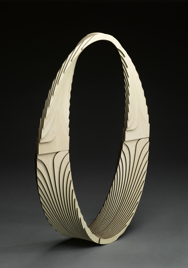
You can see that the end result has 4 quadrants. All 4 quadrants were identical.
Let me know what you think about digital fabrication. Have you seen much of it in the construction industry? Have you used it? If so, how well did it work out?
Cool..Great job. Really amazing.